


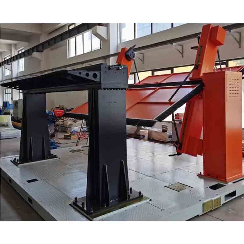
Robot Additional Axis and Positioner
The Robot additional axis and positioner is an industrial robot for welding / palletizing. Key specifications: Axes 3 axes. Lead time is 45 days; pricing is quoted per configuration. Certifications: CE documentation on request.
- Model
- N/a
- Axes
- 3 axes
- Category
- Industrial Robots
- Lead time
- 45 days
What This Platform Is For
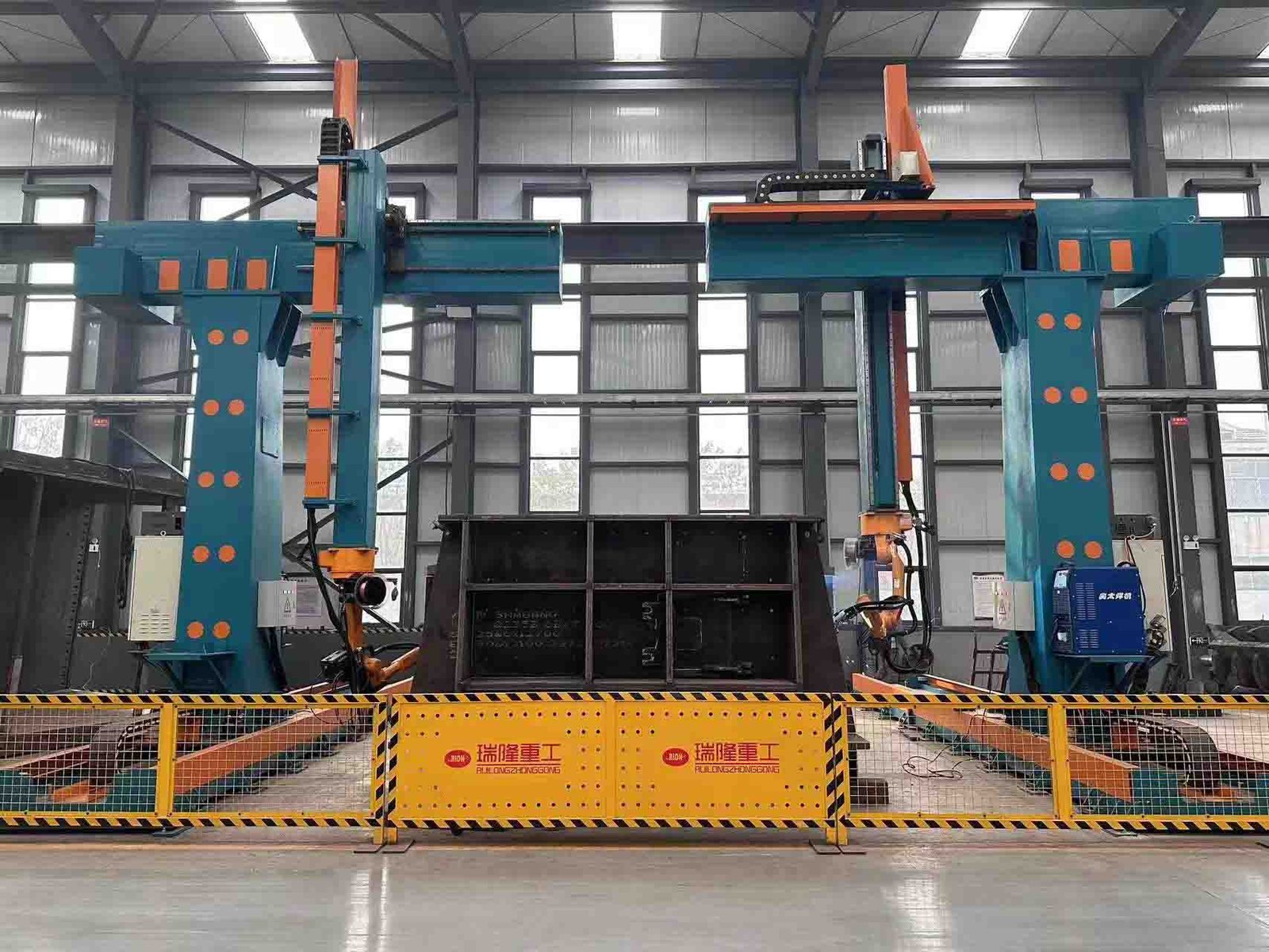
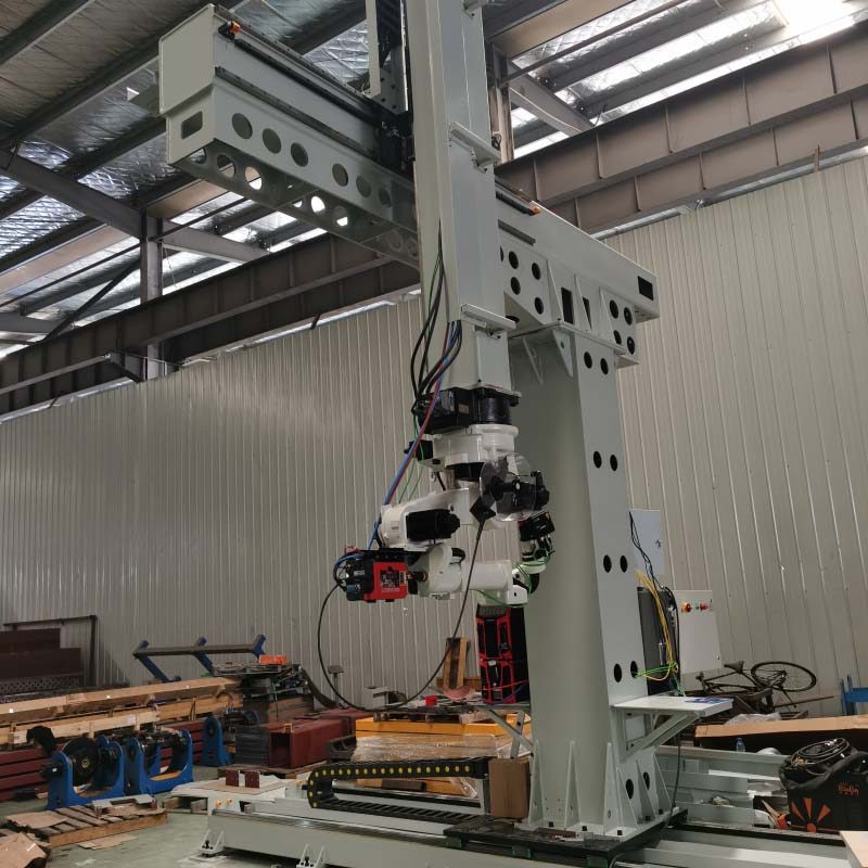
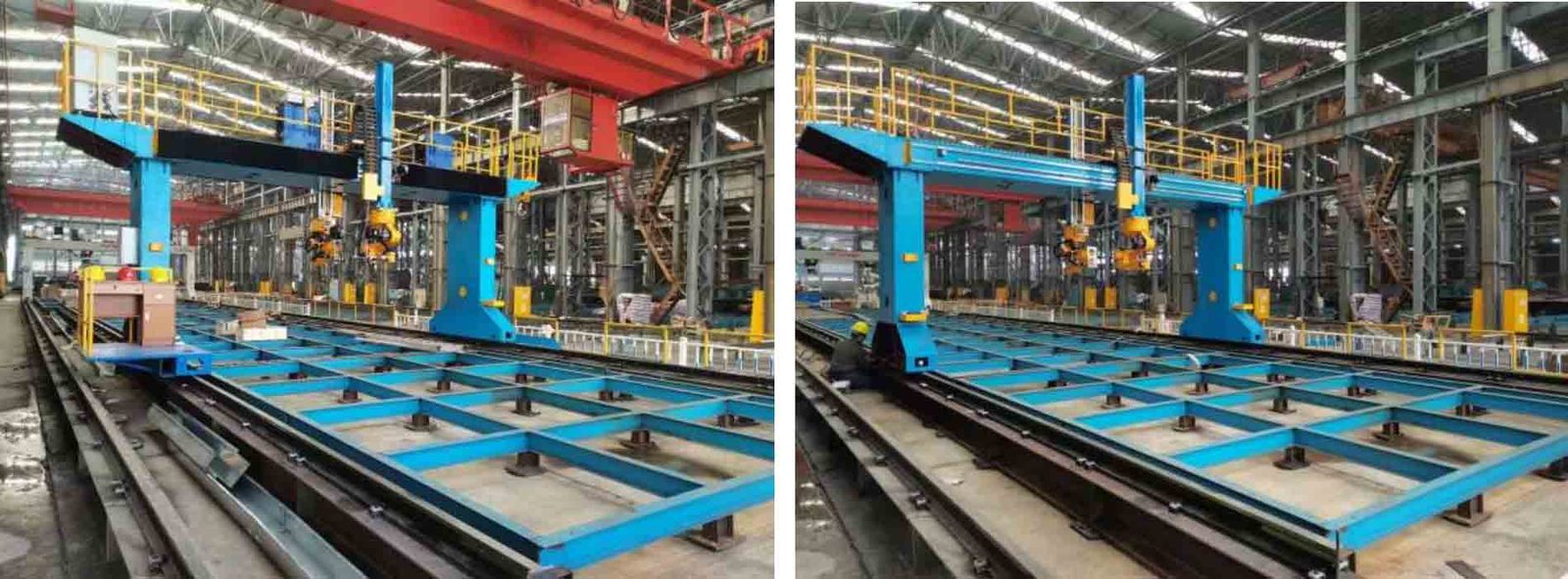
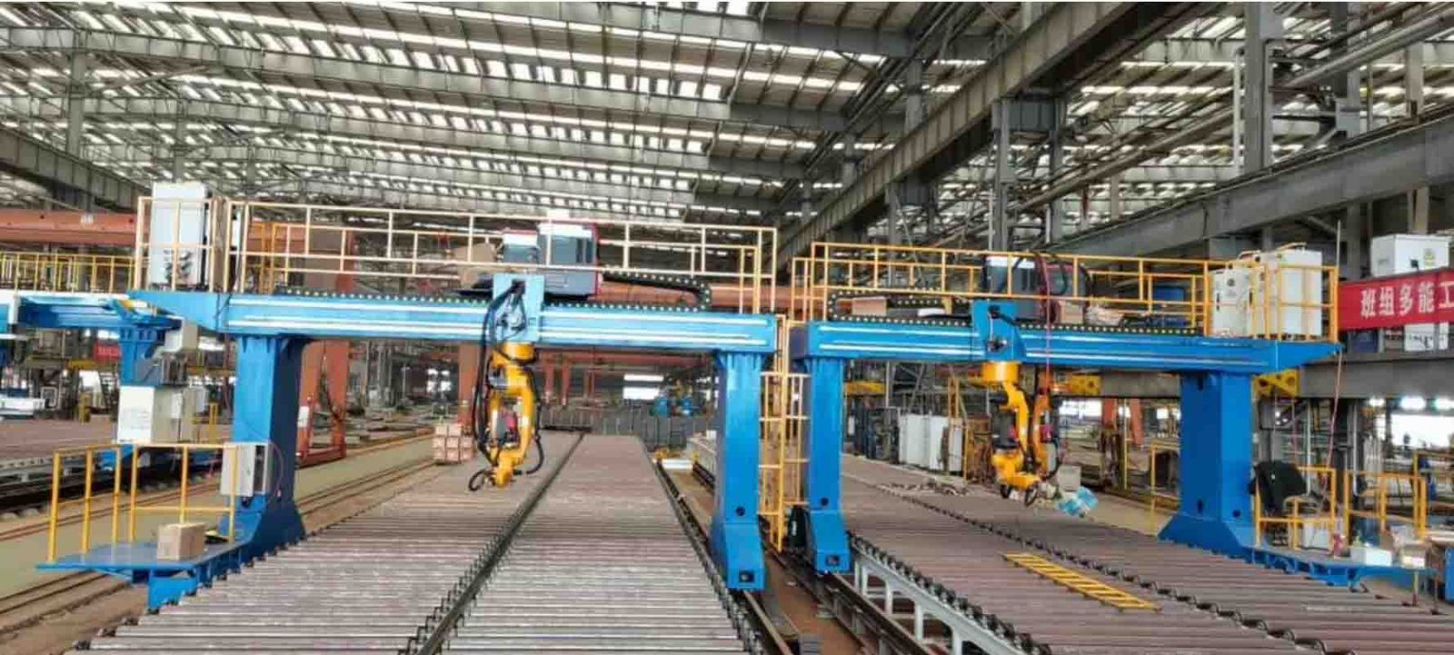
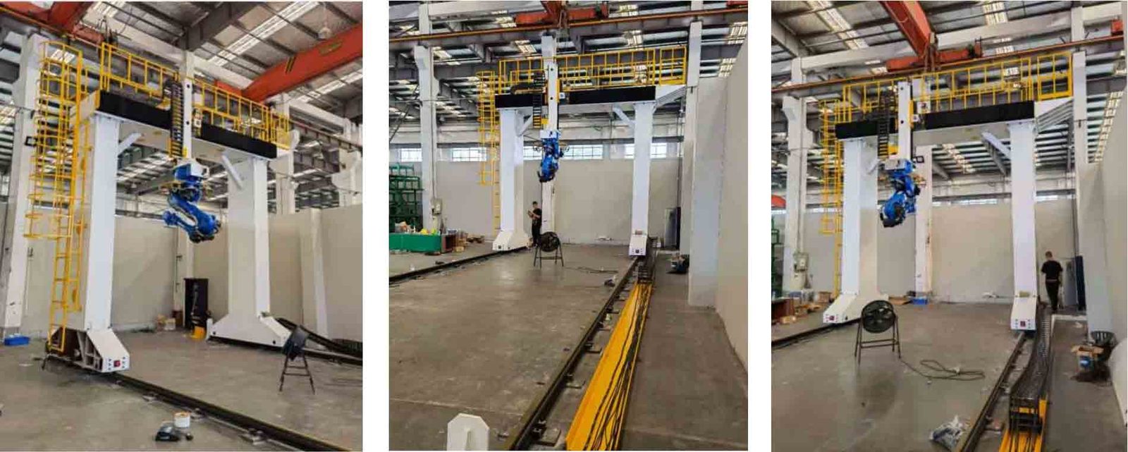
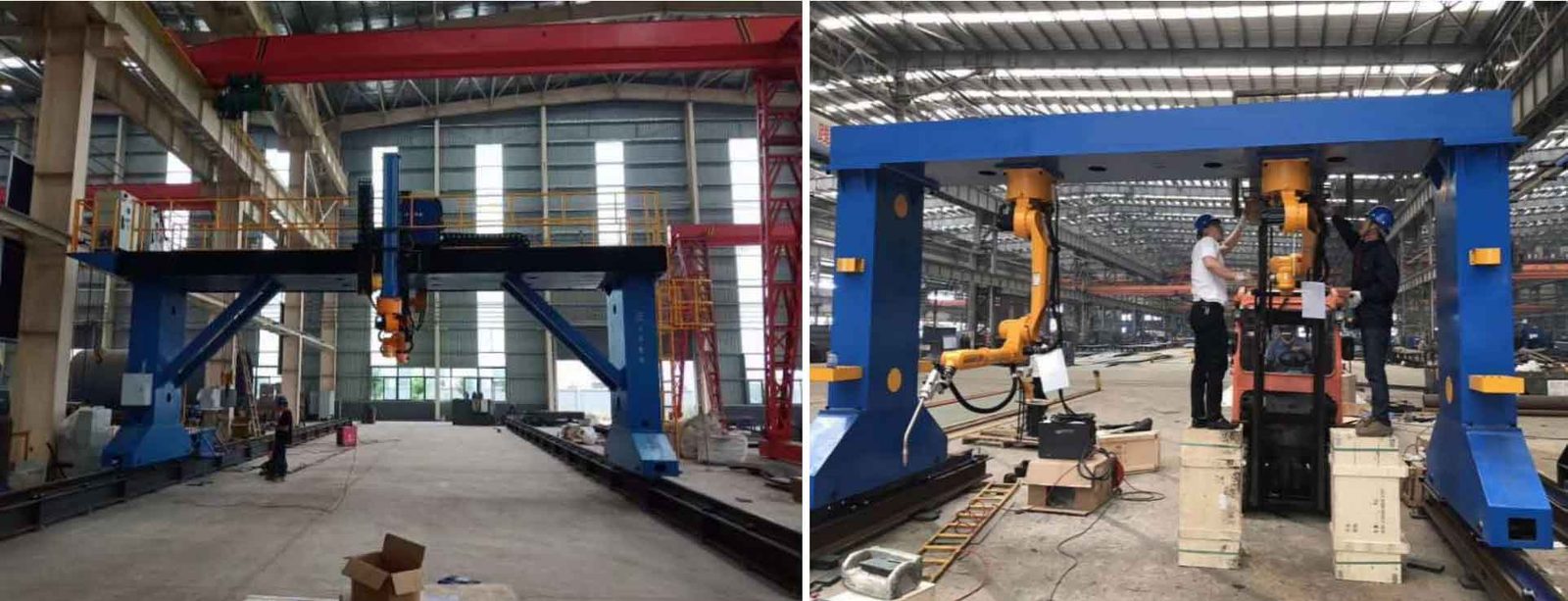
The cantilever positioner workstation is an automated solution designed for handling large, heavy, or irregular workpieces. It assists welding robots in achieving omnidirectional operations by moving, flipping, and rotating the workpiece in three-dimensional space, thus playing a crucial role in fields such as engineering machinery, shipbuilding, and wind power. Its core.
Commercial Terms
| Quotation | Priced per configuration — reply within 48 hours |
|---|---|
| Lead time | 45 days |
| MOQ | 1 unit |
| Origin | China |
| Port of loading | Shanghai, China |
| Incoterm | FOB Shanghai / CIF on request |
| Payment | 30% deposit, 70% before shipment |
| Warranty | 24 months standard, 36 months optional |
Product Details
Application notes, construction drawings and video from the TROY engineering file — the same documentation shipped with the quotation.
Structural Composition
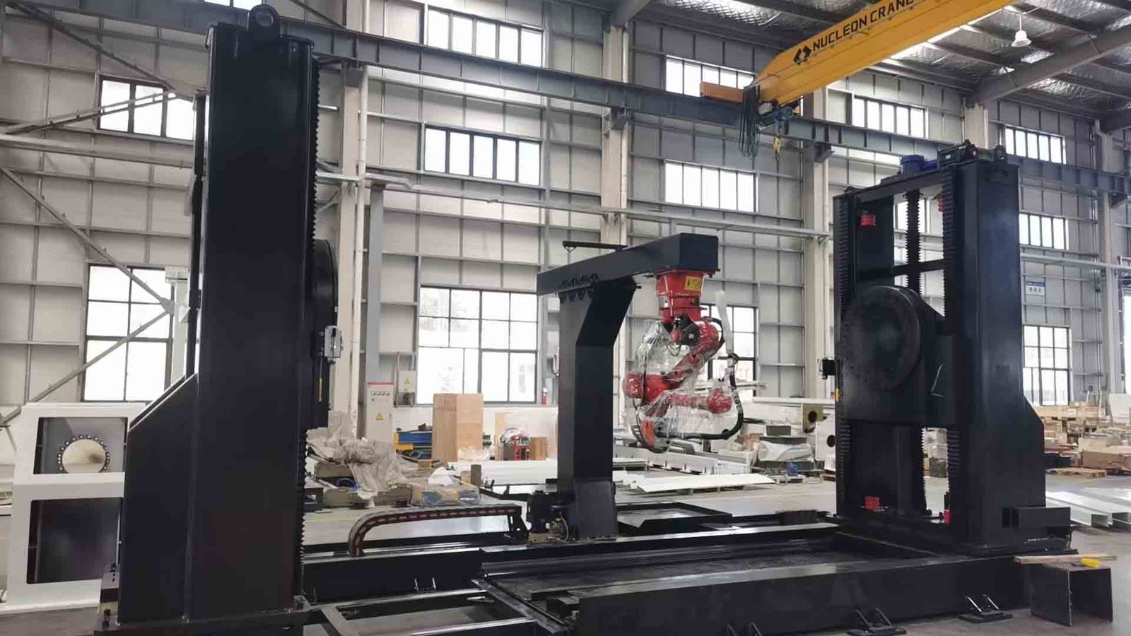
It typically consists of the following parts (the specific configuration will be flexibly combined according to actual needs):
* **Robot System:** The core execution unit of the workstation, performing welding and other process tasks.
* **Cantilever Positioner:** Carries the workpiece and enables posture changes; it's a versatile component of the workstation.
* **Mobile/Fixed Base:** Supports the positioner and workpiece, allowing the positioner to move on a track to accommodate workpieces of different lengths.
* **Integrated Control System:** Enables coordinated control and communication between the robot, positioner, and all other equipment.
* **Auxiliary Equipment:** Includes welding power supply, tooling fixtures, torch cleaning and wire cutting devices, and safety protection systems.
Core Workflow
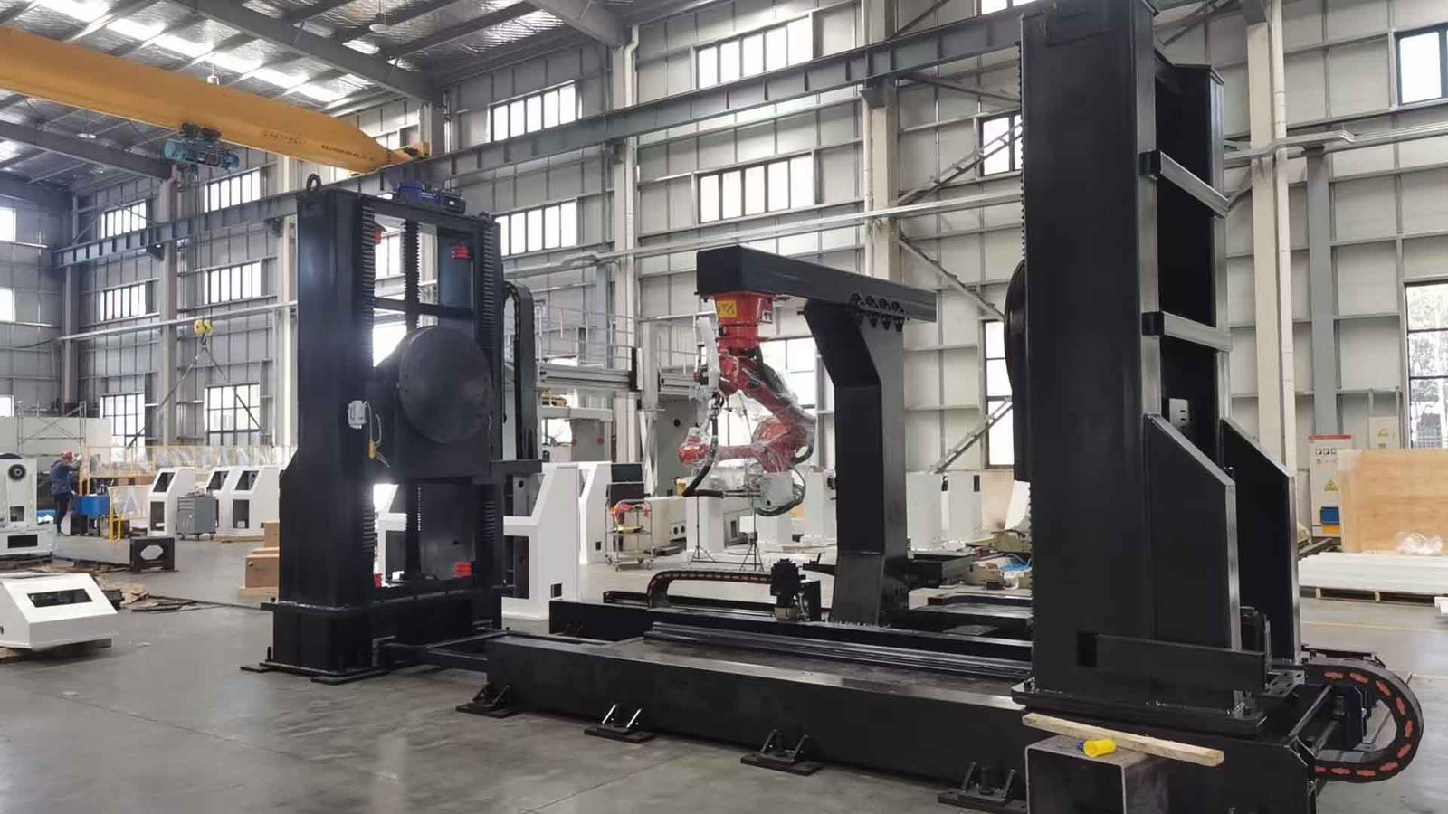
A typical workflow is as follows:
1. Workpiece Clamping: The workpiece is manually or automatically hoisted onto the positioner and clamped.
2. Collaborative Operation: The robot performs welding, and the positioner assists by flipping the workpiece to the optimal position, achieving collaborative operation where "the robot moves and the workpiece moves in tandem."
3. Unloading: After all welds are completed, the robot returns to its origin, and the workpiece is unloaded manually.
⚙ Key Technical Parameters
When selecting a positioner, the core parameters to consider (based on models such as the Kunrui RDSL-XX) include:
· Rated Load: Determines the maximum weight of the workpiece it can bear; the range can cover 500kg to 5000kg depending on the requirements.
· Lifting Stroke: The maximum vertical movement distance of the workpiece, up to 2000mm.
· Tilting/Rotation Range: Determines the ability to adjust the workpiece's posture; the tilting range is typically ±180°, and the rotation range can achieve ±360° (N×360°) continuous rotation.
• Repeat positioning accuracy: A key indicator for measuring the accuracy of a positioner. In robotic welding applications, the accuracy requirement is typically ≤ ±0.1 mm.
✨ Structural Features and Advantages
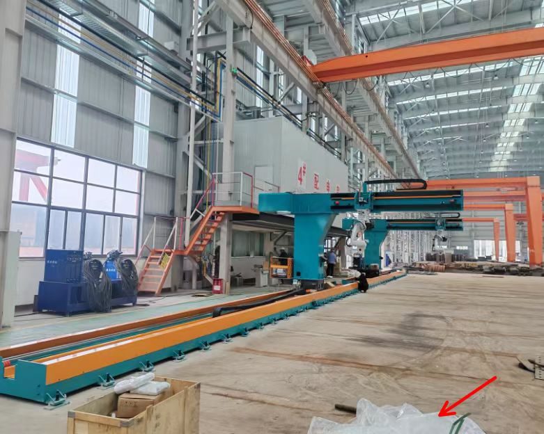
• Core feature: Lifting. The cantilever lifting mechanism, driven by servo motors and lead screws, effectively compensates for the robot's limited reach, enabling the coverage of ultra-long workpieces (e.g., up to 8 meters in length).
• Multi-axis collaboration, excellent accessibility: Through a combination of lifting, tilting, and rotating, theoretically, any surface of the workpiece can be adjusted to the optimal working position.
• Open structure: Derived from "L-shaped" and "C-shaped" designs, providing an open operating space, facilitating the lifting of large workpieces and robot operations.
• High rigidity and heavy-duty capacity: The main body is welded from high-strength steel and heat-treated to ensure structural stability and prevent vibration when bearing heavy workpieces.
• High integration and collaboration: Deeply integrated with the robot control system via Profinet, EtherCAT, and other buses, achieving precise linkage.
✨Main Application Areas
• Construction Machinery: Welding of large and complex structural components such as excavator booms and loader buckets.
• Steel Structures/Steel Profiles: Significant advantages in welding stiffening plates for long, narrow components such as H-beams and box girders.
• Wind Power Equipment: Welding of heavy components such as wind turbine towers and bases.
• Shipbuilding: Welding of heavy components such as hull sections and large containers.
• Aerospace: Assembly of aero-engine components with extremely high precision requirements.
Selection Guide.
When selecting a robot, it is recommended to evaluate it using the following steps:
1. Determine the load and workpiece dimensions: Based on the workpiece weight (it is recommended to allow for a 20%-30% margin), rotation diameter, and length, determine the required load capacity and lifting/traveling stroke.
2. Determine functional requirements: Clarify which actions to perform (lifting, flipping, rotation), and whether it is for welding (requiring low-speed stability) or assembly and handling.
3. Confirm accuracy requirements: For high-precision welding, focus on repeatability (e.g., ≤±0.1mm).
4. Evaluate control and integration methods: Confirm that the positioner is directly controlled by the robot control system and uses compatible communication protocols such as EtherCAT and Profinet.
5. Examine the quality of core components: Require suppliers to specify the brands of key components such as servo motors and precision reducers, and provide quality inspection reports.
Future Development Trends
* **Intelligent Control:** Integrating AI visual recognition and high-precision sensors, it achieves automatic workpiece identification and optimal displacement path generation.
* **High Precision and Efficiency:** Utilizing a servo motor + precision reducer combination, positioning accuracy reaches ±0.01°.
* **Modular Design:** Core components are designed as standardized modules, allowing users to flexibly combine them to meet diverse production needs and simplify subsequent maintenance.
* **Full-Process Collaboration:** Communicating in real-time with robots and other equipment via industrial Ethernet, it becomes a "production process collaborator," playing a crucial role, especially in fields like new energy.
In summary, cantilever lifting positioners are powerful tools for handling large, irregularly shaped workpieces. The core of selection is accurately matching your specific workpiece and process requirements. To help you narrow down your selection,
could you please tell me the approximate weight and length of the workpieces you mainly weld? I can then assess the suitable load specifications and stroke requirements based on your specific situation.
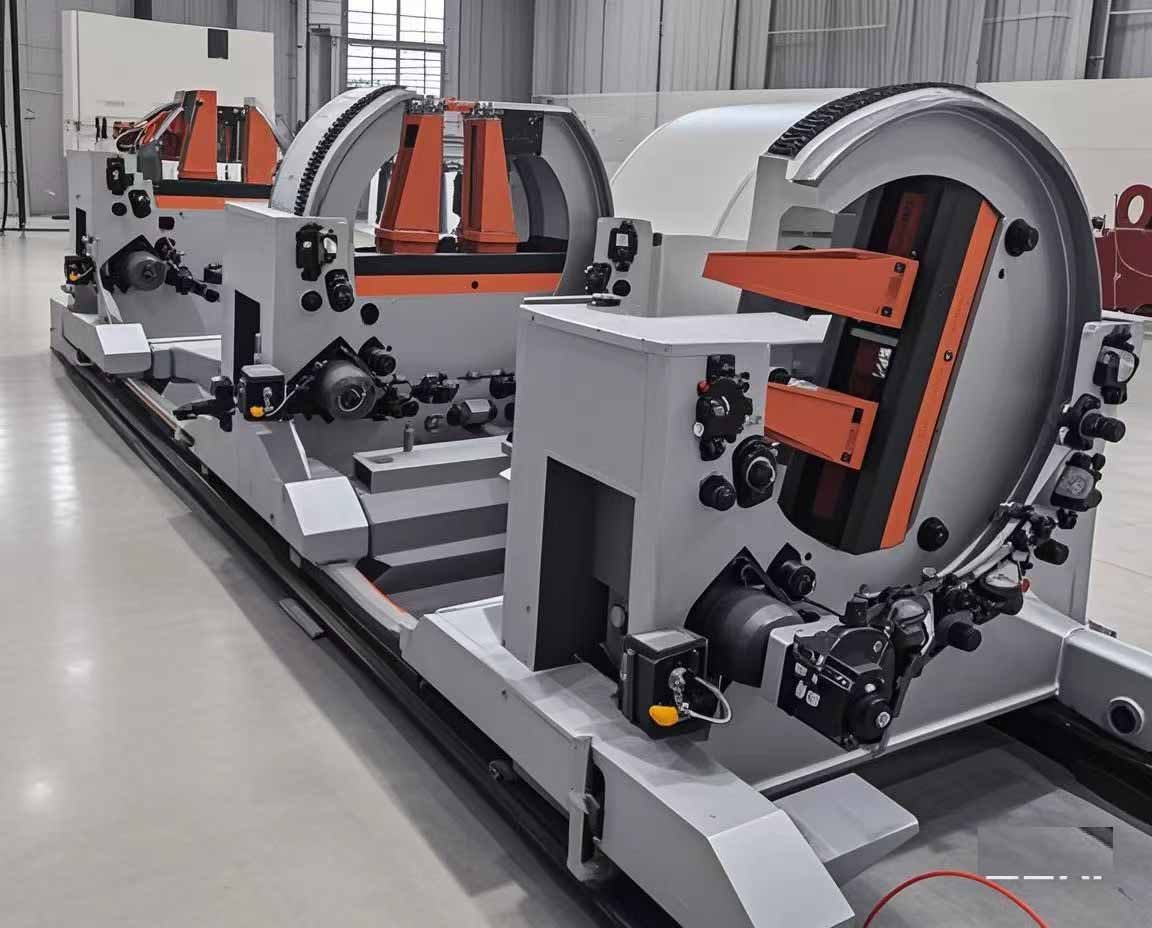
The positioner is equipped with a servo motor and RV reducer, and the parts are CNC machined for high precision.
Positioners can be designed based on technical requirements or customized according to provided drawings.
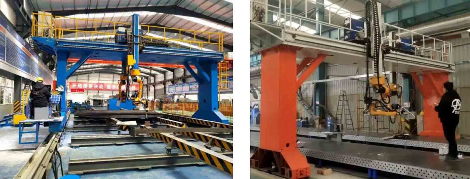
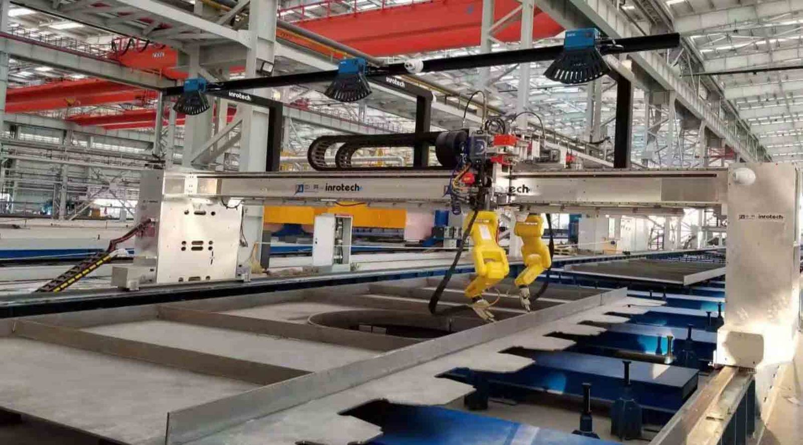
In industrial production, robots are equipped with positioners to complete tasks more accurately and efficiently. Positioners accomplish tasks by changing the position and angle of tools, allowing the robotic arm to reach more points, complete more industrial tasks, and improve production efficiency. For example, on an assembly line, robots need positioners to operate tools in different directions and angles to complete assembly tasks. On a welding production line, robots need positioners to weld items at different angles and directions. Therefore, equipping robots with positioners is crucial for their operation.
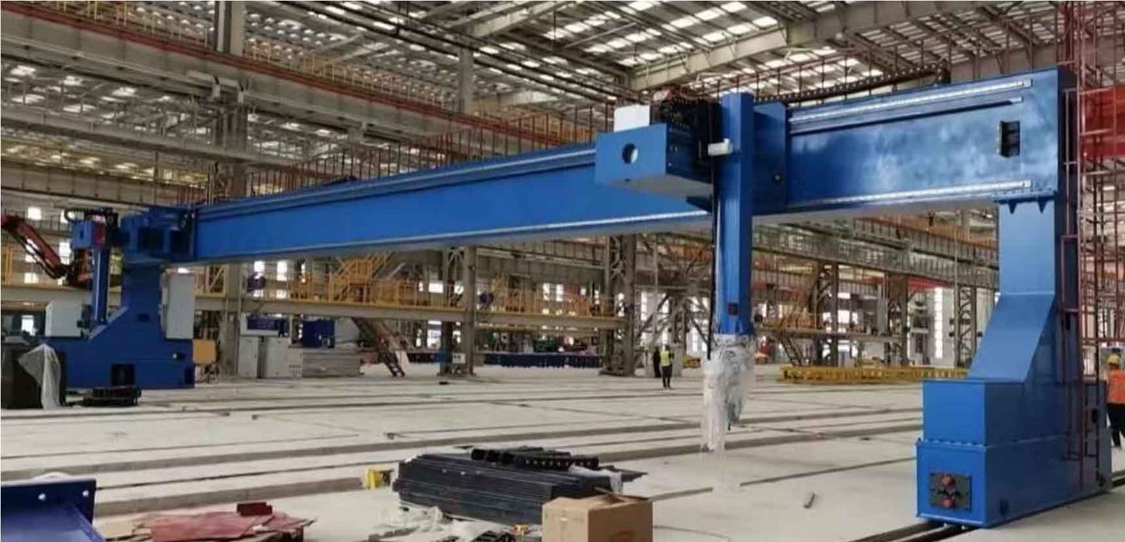
This nine-axis cantilever welding robot with no-teach programming capability offers exceptional flexibility and precision. Multiple axes provide greater degrees of freedom, enabling the robot to perform precise welding operations in a variety of complex environments. This design is typically used to handle large, heavy, or irregularly shaped workpieces, as the nine-axis configuration allows the robot to approach and weld these workpieces from multiple angles and orientations. As a no-teach robot, it eliminates the need for traditional manual programming methods.
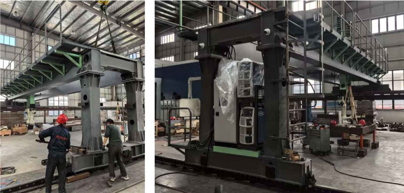
Multiple axes provide greater degrees of freedom, enabling robots to perform precise welding operations in a variety of complex environments. This design is typically used to handle large, heavy, or irregularly shaped workpieces, as the nine-axis configuration allows the robot to approach and weld these workpieces from multiple angles and orientations. The teach-free programming robot eliminates the need for traditional manual programming. It utilizes vision-based weld seam recognition and tracking, allowing the robot to autonomously identify the workpiece geometry and weld seam locations, then automatically calculate and generate the corresponding welding path. This significantly improves the automation and efficiency of welding.
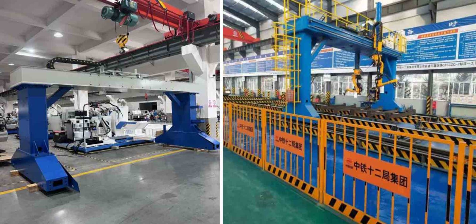
Positioners can be designed by Xinbao based on technical requirements or customized based on provided drawings.
In industrial production, robots are equipped with positioners to complete tasks more precisely and efficiently. Positioners accomplish tasks by changing the position and angle of tools, enabling robotic arms to reach more points, complete more industrial tasks, and improve production efficiency. For example, on assembly lines, robots need positioners to operate tools at different directions and angles to complete assembly tasks. On welding lines, robots need positioners to weld items at different angles and orientations. Therefore, equipping robots with positioners is crucial for their operation.
Full Technical Data
| Model | N/a |
|---|---|
| Axes | 3 axes |
| Category | Industrial Robots |
| Lead time | 45 days |
Values are nominal at 20 °C. Download the datasheet for cad models, torque curves and controller I/O maps.
Where It Runs
Sized and commissioned by TROY engineers.
Sized and commissioned by TROY engineers.
Sized and commissioned by TROY engineers.
Sized and commissioned by TROY engineers.
Buyer Questions
What are the key specifications of the ?
Axes: 3 axes. A full datasheet is available on request.
What is the lead time and MOQ for the ?
Lead time is 45 days; MOQ is 1 unit.
How is the priced?
Pricing is quoted per configuration, including tooling and freight where applicable.
Get a Priced Proposal for Industrial Robots
Include the part, target rate and destination port. An engineer — not a chatbot — replies within 48 hours.
Same Category
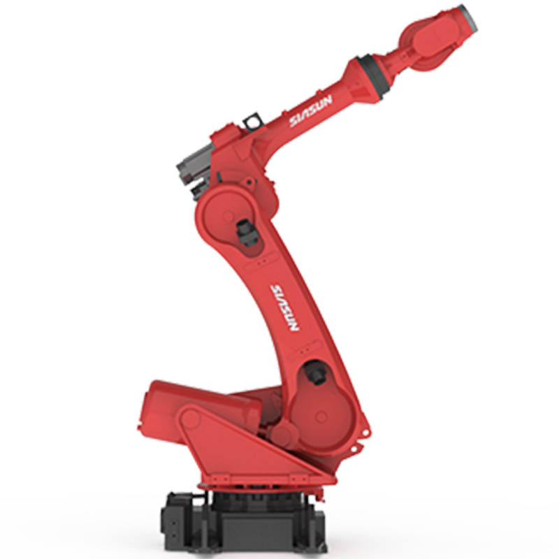
6-Axis Spot Welding Robot, 1,950 mm Reach
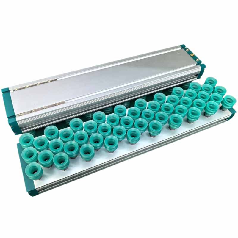
Integrated Vacuum Gripper for Robot Handling
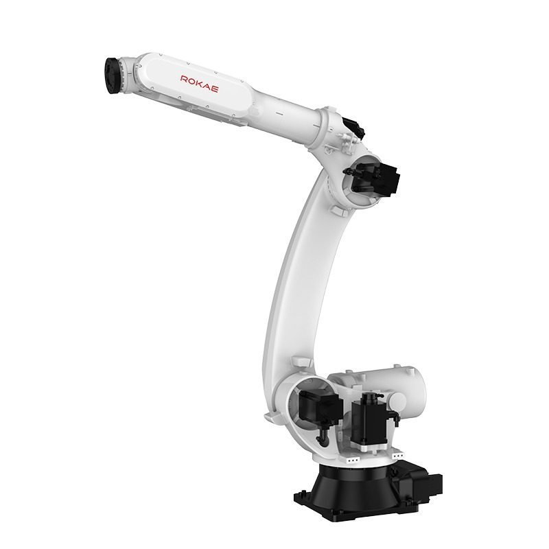
ROKAE NB220 Series 6 Axis Industrial Robot - 150kg Payload, 3201mm Reach
Reviewed by TROY Engineering · . Specifications are re-checked against the supplier datasheet at every quotation.