


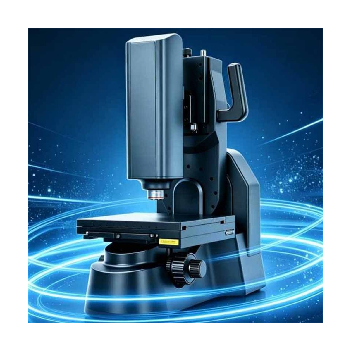
3D Super Depth-Of-Field Microscope TVN-3D3000M
The TVN-3D3000M is a microscope for PCB inspection / metrology. Lead time is 15 days; pricing is quoted per configuration. Certifications: CE documentation on request.
- Model
- TVN-3D3000M
- Lead time
- 15 days
- Category
- Electronic Microscopes & Vision
What This Platform Is For
TVN-3D3000M 3D super depth-of-field microscope: focus stacking, 3D height, roughness and blind-hole measurement, one-button 2D/3D stitching to 30, 000 pixels, 0.1 um stage, boom arm with -90 to +90 degree lens tilt.
Commercial Terms
| Quotation | Priced per configuration — reply within 48 hours |
|---|---|
| Lead time | 15 days |
| MOQ | 1 unit |
| Origin | China |
| Port of loading | Shenzhen, China |
| Incoterm | FOB Shenzhen / CIF on request |
| Payment | 30% deposit, 70% before shipment |
| Warranty | 24 months standard, 36 months optional |
Product Details
Application notes, construction drawings and video from the TROY engineering file — the same documentation shipped with the quotation.
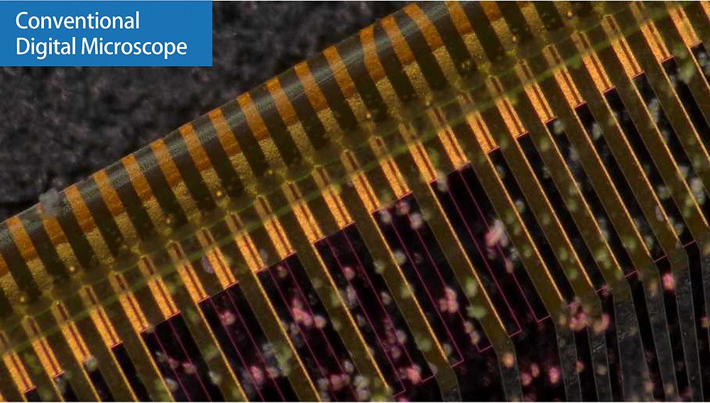
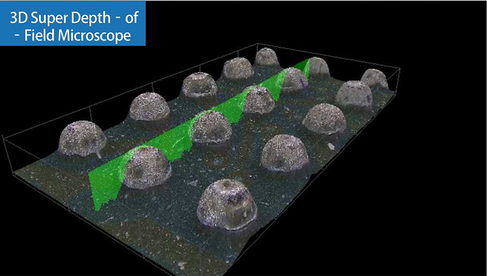
The TVN-3D3000M is a 3D super depth-of-field microscope. It takes a stack of images at successive focus heights, fuses the stack into one fully sharp frame, rebuilds the surface as a measurable 3D model and stitches large samples into a single image — focus stacking, height measurement and image stitching in one unit and one software window. A conventional digital microscope gives one in-focus plane; the TVN-3D3000M gives the whole depth of the sample, so 3D height, blind-hole depth, arbitrary-angle cross sections, surface roughness and tool edge angles become numbers instead of impressions.
Conventional digital microscope vs. 3D super depth-of-field
1. Conventional digital microscope: shallow depth of field. Only the plane in focus is sharp — slopes, deep holes and tall structures fall out of focus.
2. 3D super depth-of-field microscope: the stage scans the focus range and the software fuses every sharp region into one frame. The same stack becomes a 3D height map that can be sectioned, measured and reported.
What the 3D data is used for
1. Arbitrary-angle cross-section analysis
2. Workpiece 3D height measurement
3. Blind-hole depth
4. Surface roughness
5. Tool edge-honing angle
6. Planar-view point height and depth measurement on 2D images
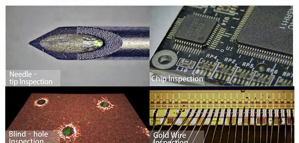
Needle tip, chip, blind hole and gold wire inspection on the same system.
2D and 3D measurement in one workflow
The system carries a full set of 2D measurement tools for length, angle, area and radius, and adds quantitative 3D analysis of depth, height and volume on focus-stacked 3D scenes. One-click operation turns the spatial data into a structured report, so the image, the cross section and the measured value stay in the same file instead of being rebuilt by hand.
Navigation focus: click the target, the stage goes there
When the magnification changes the field of view moves with it, and the navigation function puts the target area back precisely where it belongs. Click a point on the overview image and the stage travels to it and generates a fully focused fused image — no hunting for the same spot at high magnification. Where depth of field leaves part of the sample blurred, the auto-focus function returns a sharp image.
Auto-fit points instead of manual point picking
The system extracts fitting points by itself: it captures the contour edges of the sample and fits a high-precision line from N valid feature points. Operators no longer click point by point along an edge, which removes the largest source of human error in straightness, distance and angle measurements.
One-button stitching, 2D and 3D from the same pass
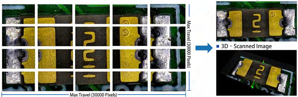
Press the stitching button and the stage scans the sample while the software joins the tiles. 3D data is acquired during shooting, so a single pass delivers both the 2D planar image and the 3D scanned image of the whole part. Stitching travel runs up to 30,000 pixels — enough to cover a full PCB or a large machined surface without giving up resolution.
Anti-glare WDR for polished metal
Solder, machined faces and polished tools throw highlights that a normal sensor clips. With WDR on, highlight and shadow detail are kept together and the image stays close to what the eye sees; with WDR off, high-contrast lighting blows out the bright areas and crushes the shadows. Illumination is 8 W bright-field plus 10 W dark-field LED at 6500 K, switchable between bright-field, dark-field and mixed illumination.
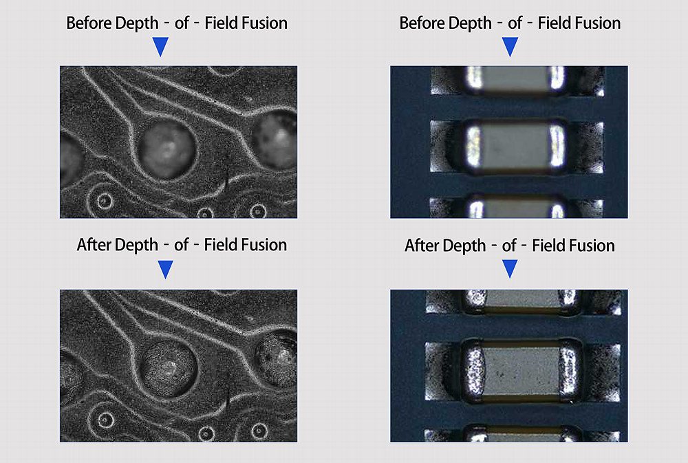
Depth-of-field fusion
A stack of images taken at different focus positions is fused into one frame in which the entire field is sharp. The comparison below shows the same fields before and after fusion: surface texture, solder joints and edges recover detail that a single shot cannot hold.
Boom-arm observation with -90° to +90° lens tilt
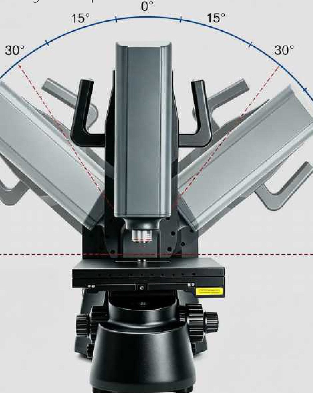
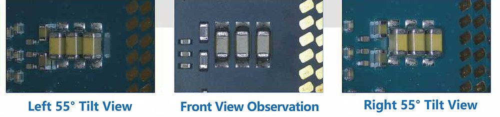
The observation head rides on a boom arm with a high-precision X, Y, Z motorized stage. Three-axis adjustment covers the field of view, the rotation axis and the tilt axis, so the lens tilts from -90° to +90° instead of the sample being tilted: left 55°, front and right 55° views of the same part come from the optics. 3D stereoscopic images are generated directly, and total magnification runs from 130× with the 5X objective up to 8800× with the 50X objective.
Configurations for different samples
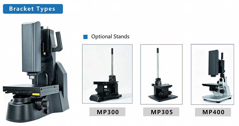
Observation stands: MP500 heavy stand as standard, with MP300, MP305 and MP400 optional. Zoom lenses: L-010 (standard) 56-490× with a 7.4-0.87 mm field of view; L-003 (optional) 550-2800× with a 0.8-0.17 mm field of view. Objectives are Plan BD 5X, 10X (standard), 20X, 50X and 100X.
| Objective | NA | Resolution | WD | Depth of field | Magnification | FOV |
|---|---|---|---|---|---|---|
| Plan BD 5X | 0.15 | 1.8 μm | 20 mm | 12 μm | 130-880× | 0.6-4 mm |
| Plan BD 10X (standard) | 0.3 | 0.9 μm | 11 mm | 3.1 μm | 270-1700× | 0.3-1.93 mm |
| L Plan BD 20X | 0.4 | 0.7 μm | 12 mm | 1.7 μm | 535-4700× | 0.14-0.99 mm |
| L Plan BD 50X | 0.5 | 0.55 μm | 10.4 mm | 1.1 μm | 880-8800× | 0.06-0.6 mm |
| L Plan BD 100X | 0.8 | 0.34 μm | 3.1 mm | 0.43 μm | — | — |
Magnification is the total system magnification with the objective in place; FOV is the field of view on the sample.
Save and share
Results leave the system as an image, a video or an Excel report, and can be shared to a network drive, a USB flash drive or a colleague in one click.
Technical specifications
| Main unit | |
| Zoom mode | Motorized zoom |
| Lens tilt angle | -90° to +90° |
| Objectives (optional) | 5X, 10X (standard), 20X, 50X |
| Sensor | 1/1.8" CMOS |
| Pixel size | 2 μm × 2 μm |
| Maximum frame rate | 30 fps |
| Resolution | 1920×1080 @ 30 fps; 2560×1440 @ 30 fps; 3840×2160 @ 30 fps |
| Bright-field light source | 8 W LED |
| Dark-field light source | 10 W LED |
| Colour temperature | 6500 K |
| Illumination mode | Bright-field, dark-field, mixed illumination |
| Sample stage | |
| Motion control | Manual / motorized (joystick) |
| XY travel | 140 × 120 mm (manual) / 80 × 60 mm (motorized) |
| XY resolution | 0.1 μm |
| XY dimensions | 220 × 220 mm |
| Load capacity | 2.5 kg |
| Z-axis motorized travel | 500 mm |
| Z-axis resolution | 0.1 μm |
| Repeat accuracy | 1 μm |
| Software functions | |
| Display | Full-screen display |
| Image split | 4-split |
| Image quality improvement | Available |
| HDR function | Available |
| Fine sharpening | Available |
| 2D stitching | Available |
| 3D stitching | Available |
| Measurement | Available |
| Auxiliary line function | Available |
| Edge finding & fitting | Available |
| Annotation function | Available |
| 2D image measurement | Available |
| 3D image measurement | Available |
| Roughness measurement | Available |
| Cleanliness measurement | Available |
Typical applications
Semiconductor and PCB: chip, gold wire, blind hole and solder bump inspection • Precision machining: tool edge, honing angle and surface finish • Materials: sandpaper, coating and surface roughness • Electronics assembly and incoming inspection • R&D and failure analysis
Manual and Catalogue Downloads
Original PDFs published on this product line — open or save directly, no form.
- TVN-SmartGO Vision Checking system manualManual · PDF 3.7 MB · 46 pages
Full Technical Data
| Model | TVN-3D3000M |
|---|---|
| Lead time | 15 days |
| Category | Electronic Microscopes & Vision |
Values are nominal at 20 °C. Download the datasheet for cad models, torque curves and controller I/O maps.
Where It Runs
Sized and commissioned by TROY engineers.
Sized and commissioned by TROY engineers.
Sized and commissioned by TROY engineers.
Sized and commissioned by TROY engineers.
Buyer Questions
What are the key specifications of the TVN-3D3000M?
Model TVN-3D3000M. A full datasheet is available on request.
What is the lead time and MOQ for the TVN-3D3000M?
Lead time is 15 days; MOQ is 1 unit.
How is the TVN-3D3000M priced?
Pricing is quoted per configuration, including tooling and freight where applicable.
Get a Priced Proposal for TVN-3D3000M
Include the part, target rate and destination port. An engineer — not a chatbot — replies within 48 hours.
Same Category
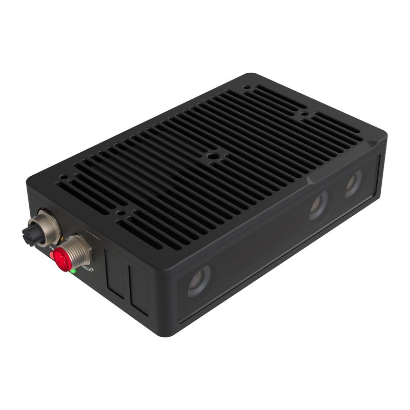
Industrial AI 3D Vision Camera - FTR855-E1, 1280x960 Depth, 0.8-4.5m Range, IP65
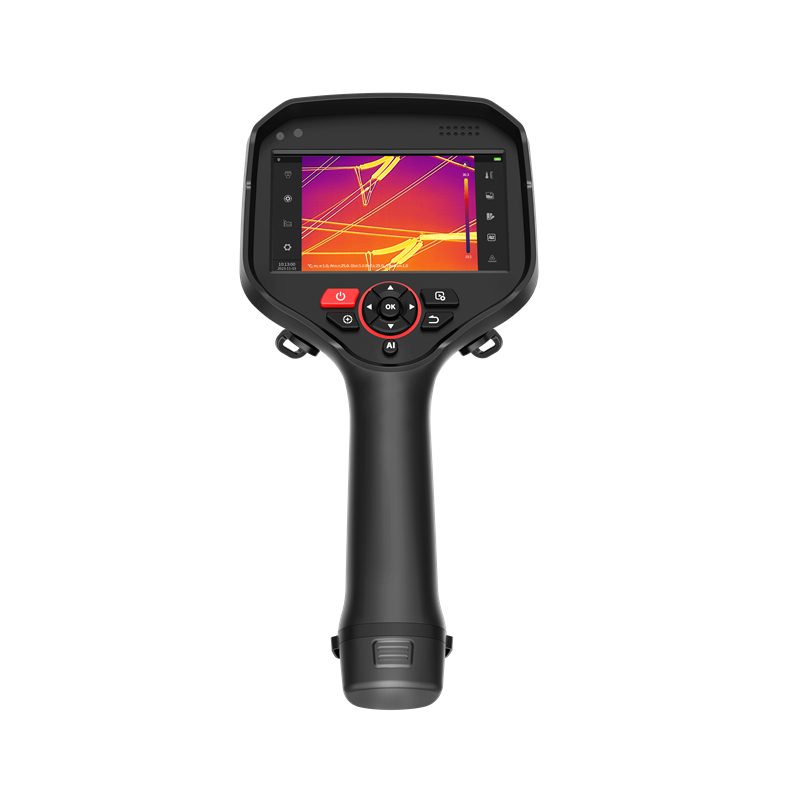
Expert Handheld Thermal Imaging Camera - RT625
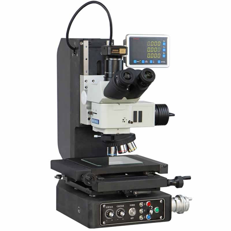
Metallographic Tool Microscope TVN-50MINI
Reviewed by TROY Engineering · . Specifications are re-checked against the supplier datasheet at every quotation.